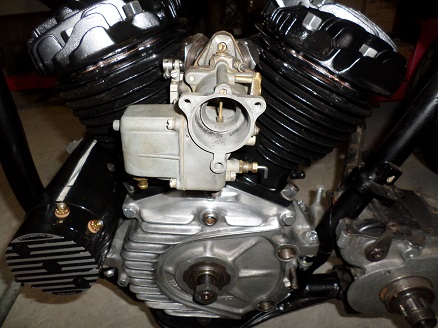
Harley Transmission Serial Numbers

Harley 4 speed transmission serial numbers. You search Auto repair manual PDF harley 4 speed transmission serial numbers, if there are search results will appear below.If search results do not exist, please search by others keyword.
5/16 Bolt hole boss clearance This can easily be checked with the trap door gasket. Put the gasket on the dowel pins. AII material of the boss around the hole that “sticks outside” the gasket (60 degrees forward to 60 degree backwards) must be removed (see figure A). Primary fork clearance Place the gasket on the housing and remove material as indicated for clearing the shifter fork (see figure B). NL PERFORMANCE PRODUCTS FOR HARLEY-DAVIDSON ® INSTALLATION INSTRUCTIONS FOR 6 SPEED CONVERSION KIT AND 6 SPEED BUILDER KIT speed transmission. Also make sure you have a 1990 or later Factory Service Manual available. Tools The conversion kit should only be used in new or low milage transmissions.
If gears or bearings of a used Gear set Removal Refer to the Factory Service Manual Section for Mainshaft and Countershaft removal. When you get to the point of actually sliding the gear set out make sure you properly mark the 5th gear set as described in the Factory Service Manual (for used transmissions only).
Further follow the factory removal procedure. Clearance Checks The 6 Speed conversion and builder kit will fit in most OEM or aftermarket transmission housings without may be needed. The following clearances must be checked before assembling the 6 speed transmission. We recommend the kits are installed by a qualified mechanic with knowledge of the Harley-Davidson 5 needed are the same as used for a 5 Speed transmission.
5 speed transmission are worn, new ones must be installed, or better, the builder kit should be used. Any modification of the housing. However due to casting differences, in some instances some modification WWW. NL PERFORMANCE PRODUCTS FOR HARLEY-DAVIDSON ® Pillow block clearance (right side) Make sure there is clearance between the pillow block and the housing.

Any clearance is O.K. (see figure C). Fork shaft support clearance Again use the gasket as the template and remove the material as indicated (see figure D). Shift drum end play The end play of the shift drum must be checked prior to final installation.
Install the shift drum. Measure the end play with feeler gauges at the right pillow block (see figure E). End play should be between.004″ and.010″, some 1/2″ X 7/8″ 0.008″ thick shims are included to adjust the end play Incoming search terms: • • • • • • • • • •. Remove Original Parts From Vehicle. 2.1 Obtain a small tube of Loctite® #262 (red) for use later.
2.2 Drain the transmission oil. 2.3 Remove the clutch adjustment cover (left side). 2.4 Remove rear exhaust header pipe (cross over exhaust pipe). 2.5 Remove the muffler support bracket. 2.6 Remove the clutch release cover (right side).
2.7 Remove clutch push rod and oil slinger. To be disassembled and modified later. 2.8 Remove the two nuts from the main (rear) and counter (front) transmission shafts. 2.9 Remove the transmission bearing housing (puller available from Champion Sidecars). To be replaced with new reverse gear transmission bearing housing (Trap Door).
2.10 Cover the exposed gears in the transmission with a cloth in preparation to cut the shifter fork shaft. 3 Install New Main and Countershaft Gears NOTE: Gears and Tapered Split Rings are factory matched sets. 3.1 Locate the shifter fork rod, mark fork rod flush at transmission case and pull out 1/4″. Figure 1 3.2 Cut the shaft at the mark and push it back in. The shaft end MUST NOT stick out of the transmission case. If the shaft is in deeper, fill the hole with silicone to prevent the shaft from moving in and out. Aplikasi edit lagu menjadi dj. NOTE: Shifter fork is made of non-tempered metal and may be cut with a hacksaw or Dremel® cutting tool.
3.3 Important: Remove stock spacers from main and counter shafts. Spray with silicon remover (Brake-Clean) then, using supplied cleaning pad, clean shafts, new counter and main shaft gears and tapered lock rings (inside and outside) Figure 1 3.4 With motorcycle in neutral, pull both the shafts out and simultaneously push the OEM outermost gears in until seated completely to expose the shoulders of both shafts. The countershaft shoulder should be flush with the gear face. For the main shaft the gear would “hang over” the shoulder a small bit.
Figure 2 3.5 Apply supplied Champion Super-Lock retaining compound to the inside and outside surfaces of the large gear tapered split ring, to the inside of the new countershaft gear (large gear) and to the transmission countershaft (the forward most shaft). 3.6 Install new countershaft gear to the transmission countershaft. Insert tapered split ring (tapered end first) into the countershaft gear. Install ring seat tool and spring to counter shaft and new countershaft gear.
- четверг 13 декабря
- 92